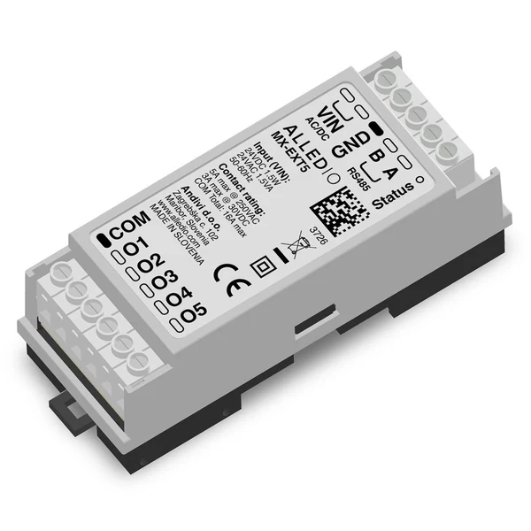
A Modbus relay module looks like the most boring device in the panel: a few relays, two RS485 wires, a slot on the DIN rail. But in HVAC and building automation it’s the point where your nicely abstracted Modbus logic meets 230 V fan motors, valve actuators and curtain drives. Pick the wrong one and the bus works fine while the field side quietly overheats a common terminal or runs two fan windings at once. This guide covers what actually matters when you pick an HVAC-grade Modbus RTU relay module: ratings, insulation, interlocking, commissioning and mechanics. We use the Alledio MX-EXT as a worked example throughout.
What a Modbus relay module actually does
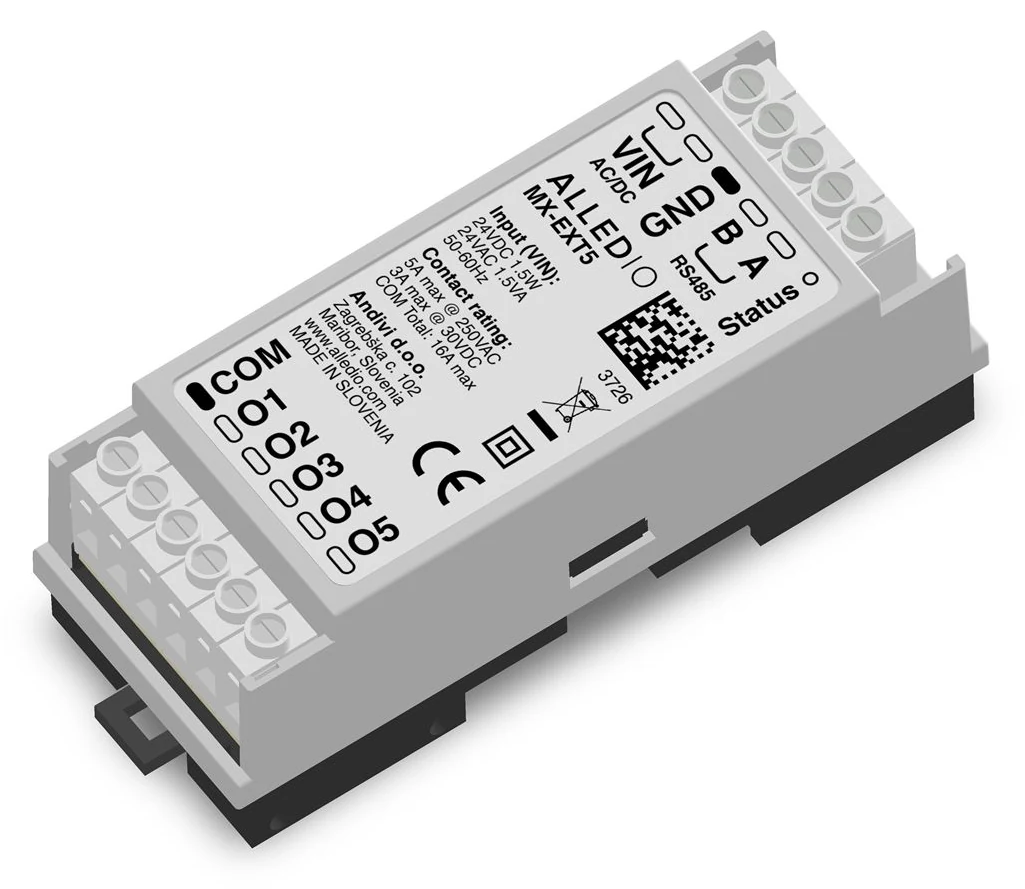
At its core, a Modbus relay module is a Modbus RTU slave with relay contacts. A master (a room controller, PLC, gateway or BMS) writes to the module over RS485, and the module opens or closes its contacts. Read requests return the current contact states. The controller decides, and the module switches the load close to where it sits.
We’ve already explained what a 5-channel Modbus relay extender is and when you need one. This article takes the next step: telling a module that belongs in a fan-coil enclosure from one that belongs on a hobby bench.
Why HVAC is a different job from “just switching relays”
Search for “RS485 relay module” and you’ll find hundreds of general-purpose boards with 8, 16 or 32 relays and generous headline ratings. Building services ask more of them:
- Mains loads next to bus wiring. Fan-coil motors, valve actuators and lighting typically run at 230 V AC, sitting a few millimetres from the 24 V supply and the RS485 pair.
- Loads that must never overlap. A 3-speed AC fan must never see two speed windings energised at once. A curtain motor must never get “open” and “close” together.
- Dozens or hundreds of identical rooms. Each one needs a predictable, repeatable relay node with a unique address and the same behaviour.
- Closed enclosures and long lifetimes. The module lives inside a fan-coil casing or a room distribution board for years.
That’s why the checklist below concentrates on the datasheet’s fine print, not the channel count.
The 8-point checklist for choosing a Modbus relay module
1. Contact ratings: per contact and through the common
Every datasheet quotes a per-contact rating. Fewer make the common terminal limit obvious, and that’s the number that bites in multi-channel modules with a shared COM.
The MX-EXT states both clearly: 5 A per contact at 250 V AC resistive (3 A at 30 V DC resistive) and 16 A maximum through COM. The limits apply at make, carry and break. In practice, five contacts at 5 A would add up to 25 A, so your combined load on the common has to stay within 16 A. When you size a fan-coil motor plus two valve actuators, add them up on the COM, not just per channel.
Durability should be specified too. The MX-EXT gives 100,000 electrical operations at 5 A / 250 V AC resistive and at least 5,000,000 mechanical operations. A datasheet without these numbers is a warning.
2. One voltage band per common
A shared COM is compact, but it has a consequence: every output on that COM must be in the same voltage band. The MX-EXT datasheet is explicit: don’t mix 230 V AC and extra-low voltage on the same COM. If your project needs both a 230 V fan and a 24 V actuator signal from one node, plan the circuits around that rule (or use separate modules) rather than discovering it during commissioning.
Protection is your job as well. On the MX-EXT, the outputs and COM aren’t fused internally, so you fit an MCB or fuse matched to the load, not exceeding 5 A per output, and any protective device on COM must not exceed 16 A. Recommended wiring is ≥ 0.75 mm² per output and ≥ 2.5 mm² for COM.
3. Insulation between the relay side and the bus side
People skip this specification. Electrical inspectors don’t. Look for a clearly stated insulation barrier between the contact circuit and the low-voltage side.
The MX-EXT uses reinforced insulation between the relay-contact circuit and the 24 V / RS485 side, designed to IEC 60664-1 for overvoltage category III and pollution degree 2 at altitudes up to 2,000 m, with a design impulse voltage of 6 kV. Construction is Class II (double insulated, no protective-earth terminal). Also note what isn’t isolated: RS485 is not isolated from VIN, and GND is a signal ground, not PE. If you want to go deeper into the insulation coordination concepts, the IEC 60664-1 standard is the reference document.
4. Supply voltage and power consumption
Most HVAC panels already carry 24 V AC, 24 V DC or both. A module that accepts either saves a power supply and a wiring mistake. The MX-EXT takes 24 V DC nominal (18–42 V, polarity-insensitive) or 24 V AC ±25 %, 50–60 Hz. Polarity-insensitive DC means one less way for an installer to get it wrong at the end of a long day.
Consumption is low: 0.2 W with contacts open, 1.5 W maximum with all contacts held. That adds up to a meaningful difference across hundreds of fan coils.
5. Interlocking built into the firmware
This is where an HVAC-focused Modbus relay module really earns its place. If the module itself refuses to close two contacts that must never be closed together, you don’t depend on every integrator’s controller program getting it right.
The MX-EXT has a firmware motor interlock with break-before-make. Contacts in a configurable “motor group” are mutually exclusive, with a dead time between releasing one contact and closing the next. By default the group is O1–O3, the three fan speeds. If a single multi-coil write tries to close more than one contact from the group, the module rejects the whole request with an exception rather than guessing.
One honest caveat, straight from the datasheet: this interlocking is an application function, not a safety function. It prevents normal control mistakes. It doesn’t replace any protective device the motor manufacturer requires.
6. A proper Modbus implementation and a published register map
“Supports Modbus” can mean almost anything. Before you buy, check three things:
- Function codes. The MX-EXT supports 01, 02, 03, 04, 05, 06, 15 and 16, so it covers coils, discrete inputs, input registers and holding registers, with single and multiple writes.
- A complete register map in the datasheet. The MX-EXT maps relays O1–O5 to coils 0–4, mirrors them as a bitfield in holding register 0, and puts configuration (slave address, motor mode, pull-in time, hold duty, motor dead time, LED mode and motor group mask) in holding registers 2–8.
- Address convention. The MX-EXT documents 0-based PDU addresses and warns that some hosts offset by one. That single sentence can save an hour of “why is relay 2 switching when I write relay 1?”
Communication defaults are address 8, 115200 baud, 8N1, with the baud rate fixed in current firmware and bus termination (none or 120 Ω) selectable over Modbus. For the protocol itself, the official Modbus specifications at Modbus.org are the definitive source.
7. Commissioning many identical devices
Factory-fresh devices all ship with the same address, which gets painful when twenty identical modules share one bus. Powering them one at a time to readdress is slow on site.
The MX-EXT offers a cleaner route: commissioning by factory serial number. Each module carries a unique 32-byte serial, readable over Modbus. You write the target serial and the new address into the commission block (holding registers 9–26), ideally in one broadcast write, and only the matching device takes the new address. Devices whose serial doesn’t match ignore the write and stay silent, so nothing collides. The datasheet also warns against writing the plain address register while several devices still share address 8. Follow that rule and commissioning stays pleasantly boring.
If you’re juggling relay nodes alongside sensors on the same network, our guide on configuring multiple Modbus sensors together covers the planning side of addressing and bus settings.
8. Mechanics, enclosure and terminals
Finally, check that the module physically fits where the job is:
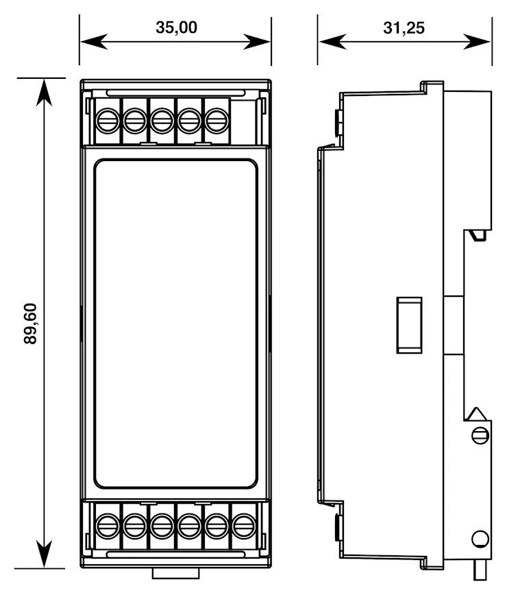
- Mounting: DIN rail EN 60715 TH35, inside a closed electrical cabinet, lockable control panel or fan-coil enclosure. Optional wall clips are for use inside the same enclosure only.
- Size and weight: 35 × 89.6 × 31.25 mm (W × H × D), about 100 g.
- Protection and environment: IP30 as installed in a closed enclosure, −20 °C to +50 °C, max. 85 % rH non-condensing, with the 5 A / 16 A ratings valid across that range.
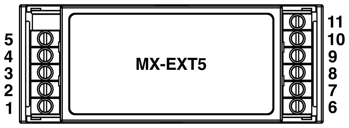
- Terminals: M2.5 screw terminals, 5.00 mm pitch, 0.05–3.31 mm² with ferrules, 0.5 N·m torque.
One module, three jobs: the application modes
General-purpose boards give you N independent channels and leave the rest to you. The MX-EXT has three application modes, selected over Modbus with the motor interlock setting and the motor group mask (holding register 8).
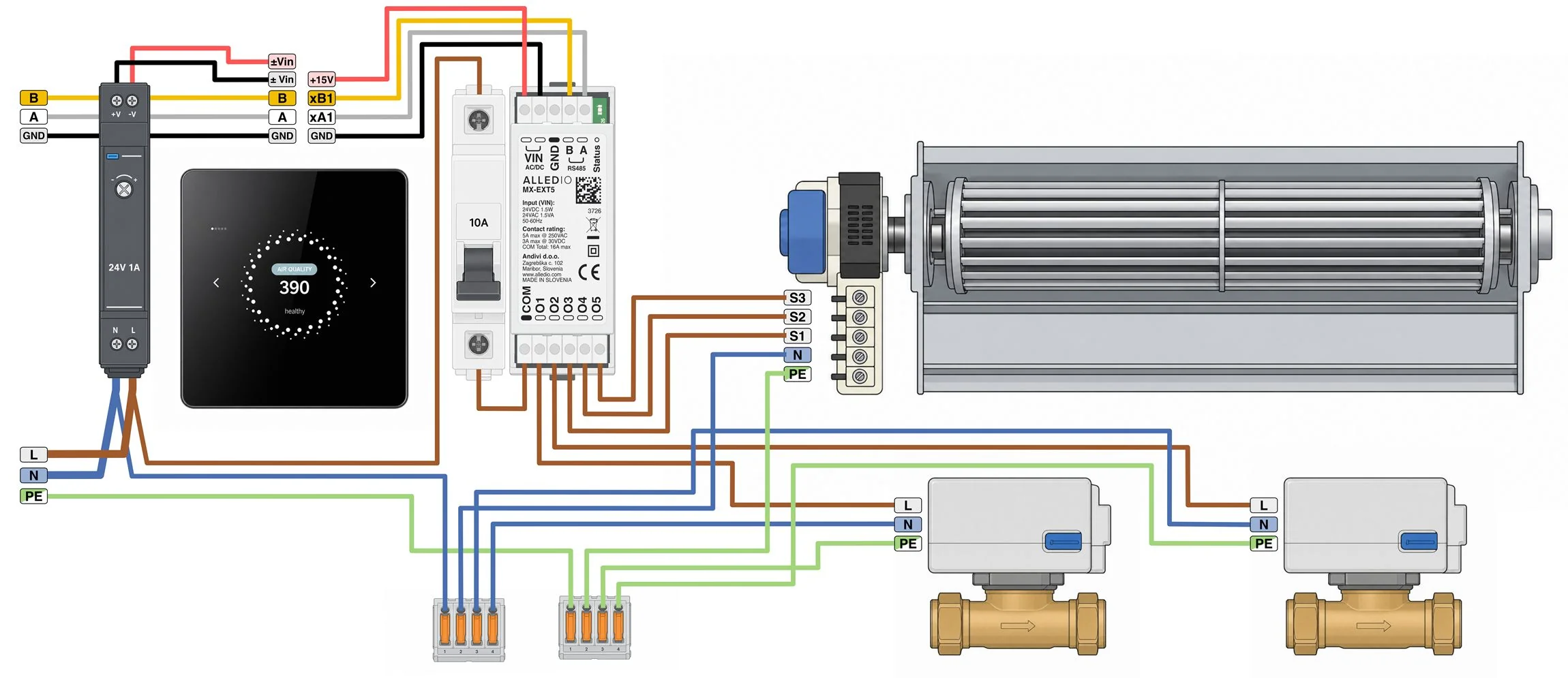
Mode 1 – Fan coil (default): 3-speed AC fan plus valves
As shipped, O1–O3 drive the three fan speeds on both variants, with the interlock active. On the MX-EXT5, O4 and O5 switch two on/off valves, for example heating and cooling. The group can be remapped if your wiring differs. The datasheet example puts the valves on O1/O2 and the fan speeds on O3–O5, with the motor group set to match. For the controller side of fan-coil projects, see our article on the OEM room controller for fan coil units.
Mode 2 – Independent relays
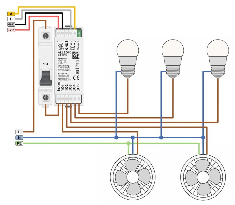
Turn the motor interlock off and you get five (MX-EXT5) or three (MX-EXT3) independent NO contacts, still limited to 5 A per contact (resistive) and 16 A through COM. Typical uses are lighting circuits and simple fan loads.
Mode 3 – Curtain-drive control
For motorised curtains, the module interlocks open/close pairs so that Open and Close are never asserted together. The MX-EXT5 handles two drives (O1/O2 and O4/O5, with O3 unused). The MX-EXT3 handles one drive on O1/O2 and leaves O3 free as a general-purpose relay.
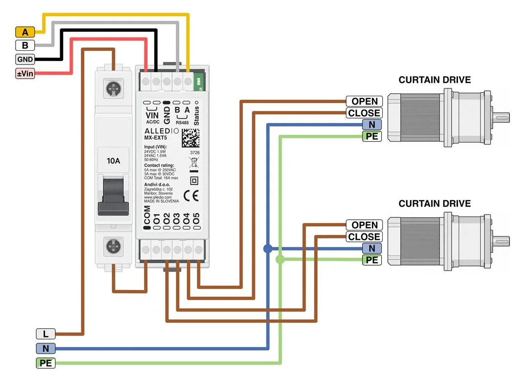
If you’d rather think of staged outputs than individual contacts, our article on staged relay control with a 5-channel Modbus extender looks at that design pattern from the control side.
MX-EXT5 or MX-EXT3: which variant?
| MX-EXT5 | MX-EXT3 | |
|---|---|---|
| Contacts | 5 × SPST-NO, shared COM | 3 × SPST-NO, shared COM |
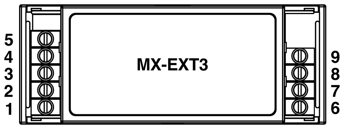
| Terminals | 1–11 | 1–9 |
| Mode 1 (default) | 3-speed fan + 2 on/off valves | 3-speed fan only |
| Mode 2 | 5 independent channels | 3 independent channels |
| Mode 3 | 2 curtain drives | 1 curtain drive + 1 free relay |
The rule of thumb is short. If the fan coil has valves that the module should switch, or you need two curtain drives, choose the MX-EXT5. If the valves are already handled elsewhere and you only need the three fan speeds, the MX-EXT3 does the job with fewer terminals to wire.
Common mistakes to avoid
- Sizing only per contact. Five “5 A” contacts don’t give you 25 A. Check the COM limit.
- Mixing 230 V and 24 V on one common. One voltage band per COM, always.
- Readdressing with several factory-fresh devices on the bus. Use serial-based commissioning instead.
- Putting Modbus on the internet. Modbus has no authentication or encryption of its own. Keep it on trusted, building-internal networks.
Frequently asked questions
What is a Modbus relay module used for in HVAC?
It lets a controller, PLC or BMS switch field loads (fan-coil fan speeds, on/off valves, curtain drives, lighting) over an RS485 Modbus RTU bus instead of through its own built-in outputs.
Is a Modbus relay extender the same as a Modbus relay module?
Essentially, yes. “Relay extender” describes the role: adding relay outputs to a controller such as the Alledio Room Unit or Room Controller. “Relay module” describes the device. The Alledio MX-EXT is sold as a relay extender for Alledio wall units but works as a standalone Modbus relay module with other Modbus controllers too.
Can a Modbus relay module switch 230 V AC loads?
Many can, but check the rating and the insulation. The MX-EXT can switch a 230 V nominal AC circuit (maximum 250 V AC) at 5 A per contact resistive, with reinforced insulation separating the contacts from the 24 V supply and RS485 side. Installation must be done by a qualified person inside a closed enclosure.
How many Modbus relay modules can I connect on one RS485 bus?
Modbus RTU allows slave addresses 1–247, and the MX-EXT accepts that full range. The practical number per segment also depends on RS485 electrical loading, cable length and termination, so plan the bus layout properly. Our article on Modbus daisy-chain connection in building automation explains the wiring side.
How do I prevent two fan speeds from switching on at the same time?
Use a module with firmware interlocking. On the MX-EXT, the default motor group (O1–O3) is mutually exclusive with break-before-make, and a write that tries to close more than one fan contact at once is rejected.
What happens to the relays if Modbus communication is lost?
Don’t design around communication loss as a safety mechanism. On the MX-EXT, removing the supply (VIN) opens all contacts, and the datasheet states that contact state on a Modbus timeout is not a safety function. Any condition that must be safe needs its own protective measures.
Conclusion: choose the small print, not the channel count
A good Modbus relay module for HVAC isn’t the one with the most relays. It’s the one whose datasheet answers the awkward questions: COM current, voltage bands, insulation, interlocking, a usable register map and a sane way to commission fifty identical units. Get those right and the module becomes a component nobody on site has to think about.
The Alledio MX-EXT was designed around exactly those questions, for Alledio room units and for any other Modbus controller. See the full specifications, wiring examples and datasheet on the Alledio MX-EXT Modbus relay extender product page, or contact the Andivi team with your project requirements.