
The Alledio MX-EXT is a standalone DIN-rail relay module for light loads in HVAC and building control. It provides switched outputs in the electrical cabinet for the Alledio Room Unit / Room Controller and for other Modbus controllers. Typical loads are fan-coil motors, on/off valves, curtain drives and lighting.
Two variants are available: MX-EXT5 with five normally-open contacts and MX-EXT3 with three. The contacts share a common COM, can switch a 230 V nominal AC circuit (contact maximum 250 V AC) and are separated from the 24 V supply by reinforced insulation.
Applications:
- Fan-coil units with a 3-speed AC fan and on/off valves (Mode 1, default)
- Independent relay outputs, e.g. lighting and fan loads (Mode 2)
- Curtain-drive control with open/close interlocking (Mode 3)
Supported Communication: RS485 Modbus RTU – as shipped: address 8, 115200 baud, 8N1
Versions:
- MX-EXT5 – 5 × NO contacts
- MX-EXT3 – 3 × NO contacts
Product Images
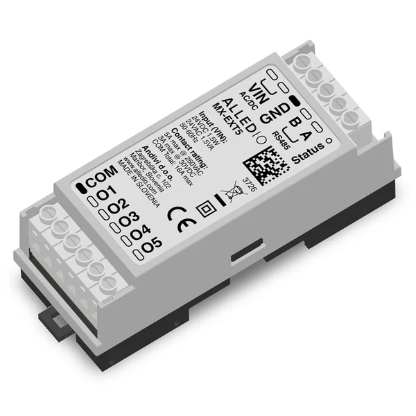
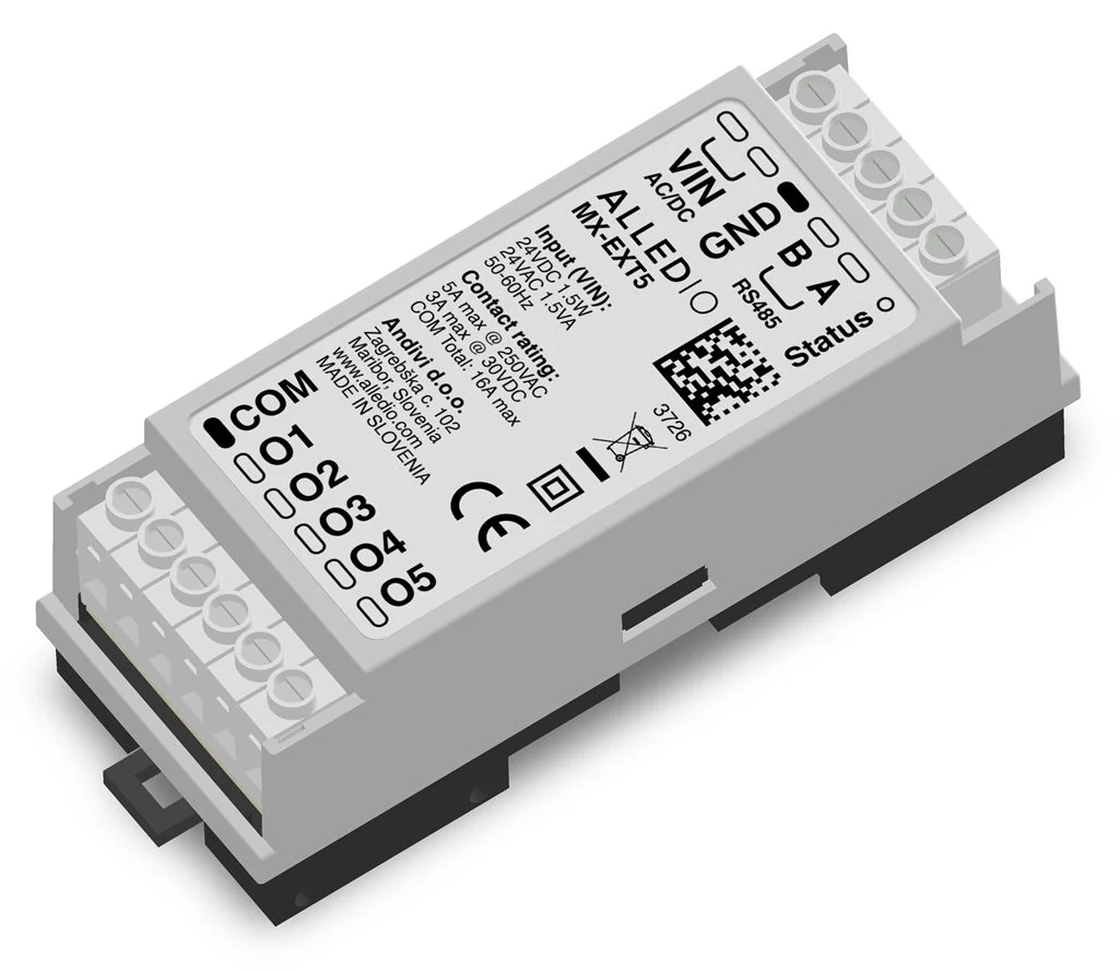
Alledio MX-EXT5 DIN-rail Modbus relay module
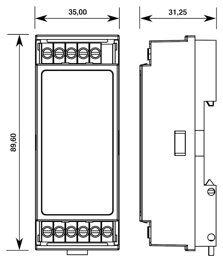
Outline drawing, 35 × 89.6 × 31.25 mm (MX-EXT5 shown, same outline for MX-EXT3)
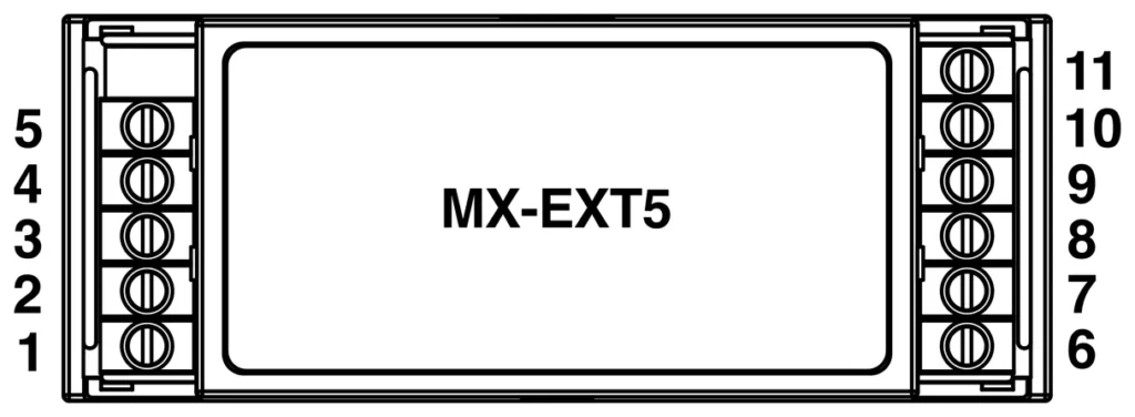
MX-EXT5 terminal layout (1–11)
Key Features
- Two variants: MX-EXT5 with 5 × SPST-NO contacts, MX-EXT3 with 3 × SPST-NO contacts, shared common COM
- Switching capacity: 5 A per contact at 250 V AC resistive, 3 A at 30 V DC resistive, max. 16 A through COM – can switch 230 V nominal AC
- 24 V supply: 24 V DC nominal (18–42 V, polarity-insensitive) or 24 V AC ± 25 %, 50–60 Hz
- Low power: 0.2 W with contacts open, 1.5 W max. with all contacts held
- Reinforced insulation between the relay-contact circuit and the 24 V / RS485 side, Class II construction
- RS485 Modbus RTU – ships at address 8, 115200 baud, 8N1; address, motor interlock and group mask set over Modbus
- Three application modes: 3-speed fan-coil (default), independent relays, curtain-drive control
- Firmware interlock with break-before-make for fan-speed and open/close contacts (application function, not a safety function)
- Compact DIN-rail housing EN 60715 TH35, 35 mm wide, for closed electrical cabinets or fan-coil enclosures
- Made in Slovenia, EU
Product number
MX-EXT5 · MX-EXT3 (article numbers and EAN pending)
Alledio MX-EXT Versions
| Variant | Role | Typical use |
| MX-EXT5 | Relay module – 5 × NO contacts, Modbus | Mode 1: 2 × valve + 3-speed fan · Mode 2: 5 channels · Mode 3: 2 curtain drives |
| MX-EXT3 | Relay module – 3 × NO contacts, Modbus | Mode 1: 3-speed fan · Mode 2: 3 channels · Mode 3: 1 curtain drive + free relay |
Technical Specifications for Alledio MX-EXT Modbus Relay Extender
| Variants | MX-EXT5: 5 × SPST-NO contacts · MX-EXT3: 3 × SPST-NO contacts. Shared common COM |
| Power supply DC | 24 V DC nominal, 18–42 V, polarity-insensitive |
| Power supply AC | 24 V AC ± 25 %, 50–60 Hz |
| Power consumption | 0.2 W with contacts open · 1.5 W max. with all contacts held at 100 % hold duty |
| Contact current | 5 A per Ox at 250 V AC resistive · 3 A at 30 V DC resistive · max. 16 A through COM. Limits apply at make, carry and break |
| Switching voltage | Can switch 230 V nominal AC; max. 250 V AC or 30 V DC. One voltage band per COM – do not mix 230 V AC and extra-low voltage |
| Intended loads | Fan-coil motors, on/off valves, curtain drives, lighting |
| Durability | Electrical: 100,000 operations at 5 A, 250 V AC resistive · 200,000 operations at 3 A, 30 V DC resistive. Mechanical: min. 5,000,000 operations |
| De-energized state | Contacts open (NO). Micro-disconnection – not a disconnecting safety device |
| Circuit protection | Ox and COM not fused. Fit an MCB or fuse matched to the load, not exceeding 5 A per Ox; any device on COM must not exceed 16 A |
| Communication | RS485 Modbus RTU. As shipped: address 8, 115200 baud, 8N1. Bus termination selectable via Modbus (none or 120 Ω) |
| Communication cable | Twisted pair with drain wire and foil wrap, or equivalent |
| LED | AUTO: breathing glow and activity. Not a contact or bus indicator |
| Bus loss | Removing VIN opens the contacts. Contact state on Modbus timeout is not a safety function |
| Isolation | Reinforced insulation between the relay-contact circuit and the 24 V / RS485 side (IEC 60664-1, OVC III, PD2, up to 2,000 m). Design Uimp 6 kV. RS485 is not isolated from VIN |
| Construction | Class II, double insulated, no protective-earth terminal |
| Housing material | DIN-rail housing. Top PC, UL 94 V-0 · bottom PPO, UL 94 V-0 |
| Ingress protection | IP30 (EN 60529) as installed in a closed cabinet or fan-coil enclosure |
| Ambient condition | −20 °C to +50 °C, max. 85 % rH, non-condensing (5 A / 16 A apply across this range) |
| Altitude | Up to 2,000 m |
| Storage | −25 °C to +70 °C, max. 85 % rH, non-condensing |
| Product dimensions | 35 × 89.6 × 31.25 mm (W × H × D) |
| Product weight | About 100 g |
| Mounting | DIN rail EN 60715 TH35, in a closed electrical cabinet, lockable control panel or fan-coil enclosure. Optional wall clips (inside the same enclosure only, not included) |
| Terminals | Screw terminals, 5.00 mm pitch, M2.5. Clamp range 30–12 AWG / 0.05–3.31 mm² (use ferrules). Strip length 6 mm. Tightening torque 0.5 N·m |
| Contact-circuit wiring | ≥ 0.75 mm² per Ox · ≥ 2.5 mm² for COM |
| Type of action | Type 1 (operating control), not a protective control. Software class A |
| Standards | EMC Directive 2014/30/EU, Low Voltage Directive 2014/35/EU, RoHS Directive 2011/65/EU as amended by (EU) 2015/863, WEEE 2012/19/EU. Assessed to EN IEC 60730-1:2024/A11:2024, EN IEC 61000-6-2:2019, EN IEC 61000-6-3:2021, EN IEC 60664-1, EN 60068-2-1, -2-2, -2-14, -2-78, EN IEC 63000:2018 |
| Country of origin | Slovenia, EU |
| Warranty | 1 year |
Application Modes
Both variants ship in Mode 1 (motor interlock on, motor group O1–O3). The mode is set over Modbus via the motor interlock and the motor group mask (holding register 8).
Mode 1 – Fan coil (default): 3-speed AC fan + valves
Intended for fan-coil applications with a 3-speed AC fan, connected over Modbus to the Alledio Room Unit / Room Controller or to other controllers. As shipped, O1–O3 drive the three fan speeds on both variants; on MX-EXT5, O4 and O5 control two on/off valves. MX-EXT3 has no valve contacts. Firmware interlocking prevents simultaneous activation of the contacts in the motor group.
Mode 2 – Standalone relay: 5 or 3 channels
Independent NO contacts (MX-EXT5: five channels, MX-EXT3: three), still limited to 5 A per contact (resistive) and 16 A through COM. Turn the motor interlock off over Modbus.
Mode 3 – Curtain control: 2 drives or 1 drive + free relay
MX-EXT5 connects up to two curtain drives on pairs O1/O2 and O4/O5; O3 remains unused. MX-EXT3 connects one drive on O1/O2; O3 remains a free general-purpose relay. Open and Close are never asserted together. Set the motor group mask to the open/close pair in use.
Fan-speed and curtain interlocking is an application function, not a safety function.
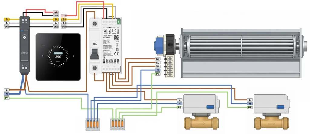
Mode 1 example on MX-EXT5 (remapped: valves on O1/O2, fan speeds on O3–O5, motor group O3–O5)
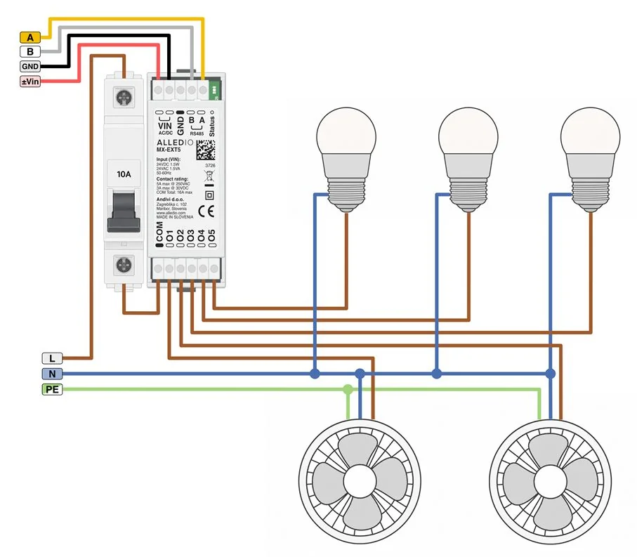
Mode 2 example on MX-EXT5 – lighting and fan loads (example, not a factory wiring)
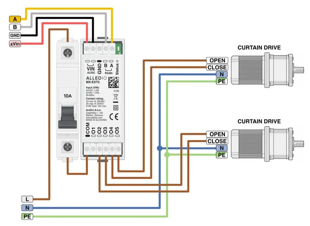
Mode 3 – curtain control with two drives on MX-EXT5
Terminal Assignment
Supply and bus terminals are the same on both variants. Both variants ship in Mode 1.
| Terminal | Name | Function (both variants) |
| 1, 2 | VIN | Supply, 24 V DC nominal (18–42 V) or 24 V AC ± 25 %. Polarity-insensitive – DC may be connected either way |
| 3 | GND | Signal ground. Not a protective earth. Recommended on long runs or where devices use different supplies |
| 4 | B | RS485 B |
| 5 | A | RS485 A |
MX-EXT5 · COM, O1–O5
| Term. | Name | Mode 1 | Mode 2 | Mode 3 |
| 6 | COM | Common | Common | Common |
| 7 | O1 | Motor – stage 1 | Relay 1 | Motor – open 1 |
| 8 | O2 | Motor – stage 2 | Relay 2 | Motor – close 1 |
| 9 | O3 | Motor – stage 3 | Relay 3 | Unused |
| 10 | O4 | Valve | Relay 4 | Motor – open 2 |
| 11 | O5 | Valve | Relay 5 | Motor – close 2 |
MX-EXT5 terminal layout (1–11)
MX-EXT3 · COM, O1–O3
| Term. | Name | Mode 1 | Mode 2 | Mode 3 |
| 6 | COM | Common | Common | Common |
| 7 | O1 | Motor – stage 1 | Relay 1 | Motor – open |
| 8 | O2 | Motor – stage 2 | Relay 2 | Motor – close |
| 9 | O3 | Motor – stage 3 | Relay 3 | Relay 3 · free |
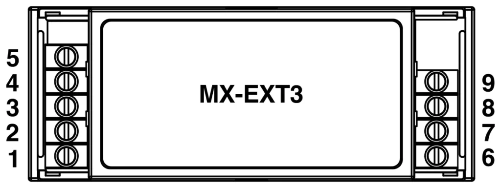
MX-EXT3 terminal layout (1–9)
Loads connect between each Ox contact and COM. Combined current through COM max. 16 A. All Ox that share COM must be in one voltage band – do not mix 230 V AC and extra-low voltage on the same COM. Ox contacts and COM are not fused; fit an MCB or fuse matched to the load, not exceeding 5 A per Ox. Recommended wire size: ≥ 0.75 mm² per Ox and ≥ 2.5 mm² for COM.
Modbus Communication
The MX-EXT communicates over RS485 Modbus RTU. Slave address, motor interlock and motor group are set over Modbus; supported function codes are 01, 02, 03, 04, 05, 06, 15 and 16. The complete Modbus register map is included in the datasheet.
| Parameter | Options | As shipped |
| Baud rate | 115200, fixed in current firmware | 115200 |
| Framing / format | RTU, 8 data bits, no parity, 1 stop bit | 8N1 |
| Address | 1–247, stored in EEPROM | 8 |
| Motor interlock | Off = independent contacts (Mode 2) · On = contacts in the group are mutually exclusive, break-before-make | On |
| Motor group | Bit mask of contacts in the interlock group | O1–O3 |
| Termination | Selectable via Modbus: none or 120 Ω | None |
Commissioning: factory-fresh devices share address 8. Commission one device at a time by its factory serial number (holding registers 9–26) and do not write the address register while several devices still share address 8. Connect Modbus only to trusted, building-internal networks.
Device Size
Outline drawing, 35 × 89.6 × 31.25 mm (MX-EXT5 shown, same outline for MX-EXT3)
Installation and Safety
- Install only in a closed electrical cabinet, lockable control panel or fan-coil enclosure on DIN rail EN 60715 TH35; terminals must not be accessible to untrained persons, and the enclosure must keep the module non-condensing.
- Terminals COM and O1–O5 (MX-EXT5) or COM and O1–O3 (MX-EXT3) may carry 230 V AC. Installation and service by a qualified person only, with all supplies isolated.
- Modbus has no authentication or encryption of its own – do not expose it to the public internet.
Datasheet MX-EXT – Alledio MX Modbus Relay Extender

Works with Alledio Room Unit and Room Controller
The MX-EXT provides switched outputs in the electrical cabinet for the Alledio OEM Room Unit and the Alledio OEM Room Controller, and connects over RS485 Modbus RTU. In Mode 1 it drives the three fan speeds of a fan-coil unit and, on MX-EXT5, two on/off valves – while the wall unit keeps the user interface and control logic in the room. It can also be used with other Modbus controllers.
About Alledio
Alledio is an OEM brand engineered and developed by Andivi, headquartered in Maribor, Slovenia. As your strategic partner, Alledio delivers pre-engineered, market-ready solutions that streamline development timelines, reduce deployment risk, and ensure high-level compatibility across HVAC platforms.

Alledio by Andivi
TALK TO AN EXPERT
Interested in our products? Looking for options or a specific quote? Contact us with your custom enquiry!
Explore Other Alledio OEM Products for HVAC manufacturers

Alledio OEM Room Unit
Alledio OEM Room Unit The Alledio OEM Room Unit, by Andivi, is a highly advanced OEM room controller designed for maximum efficiency and seamless integration. It features a modular, firmware-driven architecture with an adaptable user interface, enabling straightforward customization for diverse application requirements. Delivered as a pre-engineered, off-the-shelf solution, the Alledio OEM Room Unit ensures…
Alledio OEM Room Controller
Alledio OEM Room Controller The Alledio OEM Room Controller is a sophisticated solution designed for seamless integration within HVAC systems. Built on a modular, firmware-driven architecture, the controller combines advanced functionality with intuitive usability and can reliably operati in several scenarios. The Room Controller features integrated sensors for temperature, humidity, and optional CO2 and volatile…

Alledio OEM Thermostat with Modbus
Alledio OEM Thermostat with Modbus and 3 Fan Speeds The Alledio OEM Thermostat offers unparalleled flexibility as a premier OEM Modbus thermostat, engineered for HVAC manufacturers seeking a customizable and adaptable solution. Featuring a fully brandable user interface and adaptable firmware, it serves as a sophisticated, off-the-shelf solution that is ready for immediate and seamless…

Alledio BACnet Particulate Matter – PM2.5 sensor (indoor) – ANB-THPM2.5
Application – BACnet Particulate Matter – PM2.5 sensor for indoor use The BACnet Particulate matter Sensor for indoor applications combines the measurement of temperature, relative humidity, and particulate matter (PM2.5) detection. This multi-sensor device supports both BACnet MSTP and BACnet IP protocols. The ANB-THPM2.5 is designed for building automation in offices, schools, healthcare facilities, residential…

Alledio BACnet Air Quality VOC sensor (indoor) – ANB-THPV
Application – BACnet Air Quality Sensor (VOC) for indoor use Bacnet Air Quality Sensor (VOC) for indoor application is a sensor combining the measurement of temperature, relative humidity, pressure and Air Quality (VOC; computing Air Quality Index). This sensor device enables you to choose between the BACnet MSTP and BACnet IP protocols. The ANB-THPV is…

Alledio BACnet CO2 Sensor – ANB-THPC
Application – BACnet CO2 Sensor for indoor use Alledio Bacnet CO2 Sensor THPC for indoor application is a sensor combining the measurement of CO2 (ppm), temperature (°C) and relative humidity (%). This sensor device enables you to choose between the BACnet MSTP and BACnet IP protocols. The ANB-THPC is meant to be used for building…