A new device is on the trunk. The BMS says “offline”. Is it the wiring, the settings, or the device? This guide shows you how to test Modbus RS485 communication in seven clear steps, from the cable to a logged result.
You need a laptop, a USB to RS-485 adapter and a Modbus RTU tester. We use ModbusMate, our free tester that runs in the browser. The steps work with any good tool, though.
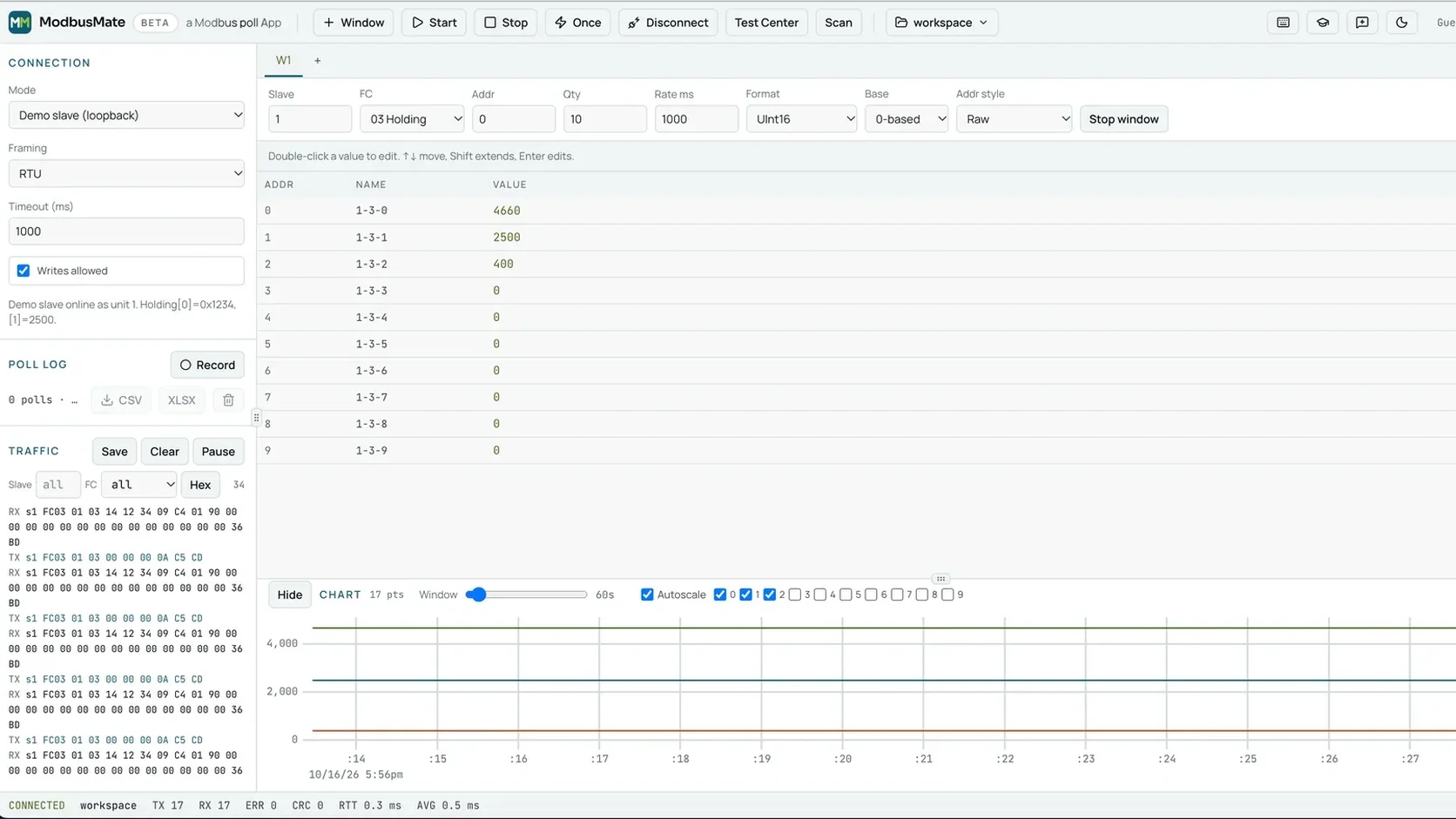
What you need before you start
Get these ready first. It saves trips back to the van.
- A USB to RS-485 adapter. Any adapter your computer shows as a serial port works. Common ones use FTDI, CP210x or CH340 chips.
- A browser. Chrome, Edge or Opera on a desktop or laptop. Firefox and Safari do not support Web Serial.
- The device datasheet. You need the slave address, baud rate, parity, stop bits and the register map.
- Access to the bus. Ideally at a junction box, so you can test a single device or a whole segment.
Step 1: Check the wiring
Most RS-485 faults are wiring faults. Check three things:
- A and B are not swapped. Labels differ between makers. If nothing answers, swapping the pair is a fast test.
- Ground or common is connected where the device asks for it.
- Termination is right. The line should be terminated at both ends, not in the middle.
The Modbus serial line spec also limits a segment to 32 devices without a repeater. Our deep dive on Modbus busline device limits and interference explains the details. For chain wiring, see Modbus daisy chain connections.
Step 2: Match the serial settings
Master and slave must agree on every setting. One wrong value and you get silence or garbage.
- Mode: RTU or ASCII.
- Baud rate: ModbusMate supports 300 to 3,000,000.
- Parity and stop bits: for example even parity and 1 stop bit.
- Slave address: 1 to 247. Address 0 is broadcast and gets no reply.
Not sure what the device uses? Our guide to key Modbus settings for sensor configuration lists the usual suspects.
Step 3: Connect and poll one known register
Open ModbusMate and pick your serial port. Enter the settings from Step 2. Then add one poll window:
- slave ID from the datasheet,
- function code 03 (read holding registers) or 04 (read input registers),
- a start address you know exists,
- a small quantity, such as 2 to 10 registers.
Press F5 to start polling. Values that arrive turn green. That is your first proof that the link works.
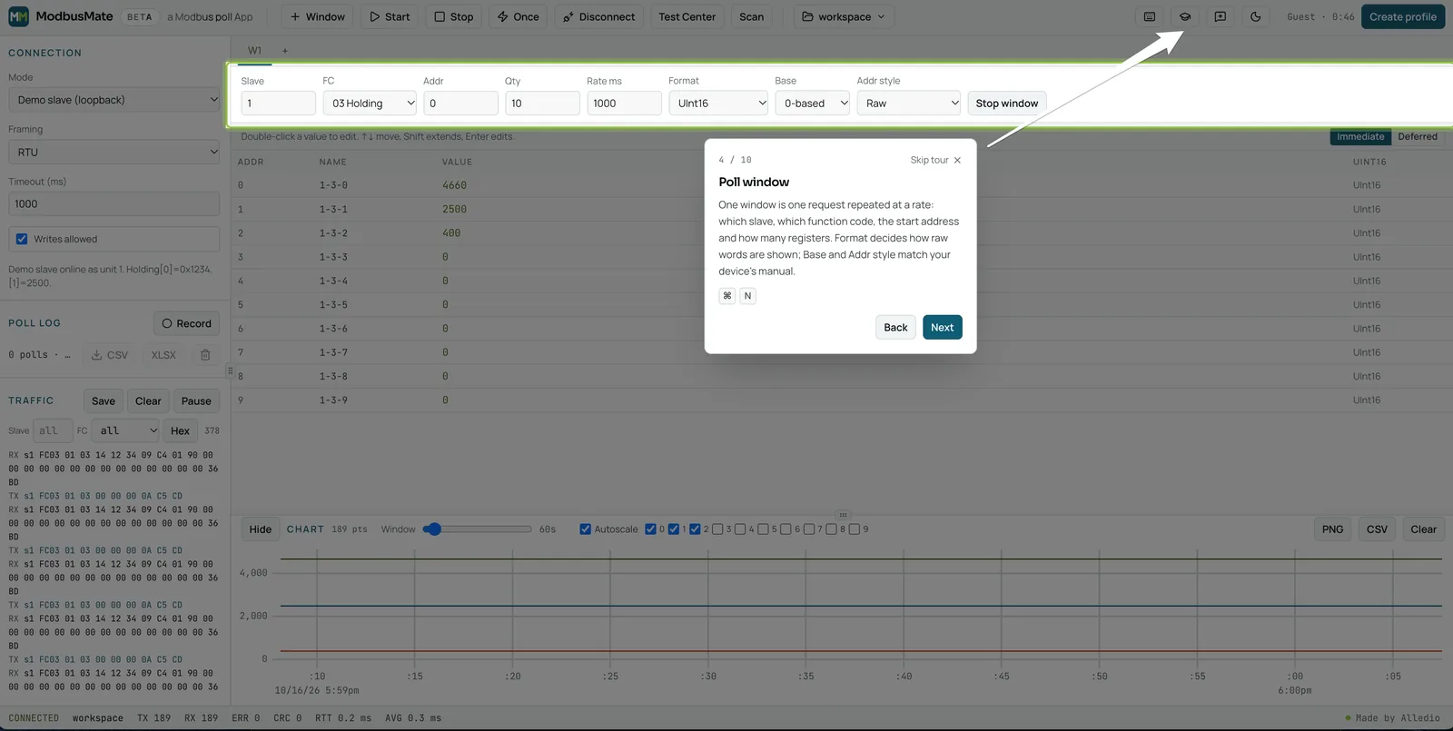
Step 4: Read the counters
Now look at the status bar. ModbusMate counts TX, RX, errors, CRC failures and round-trip time. These numbers tell you more than any LED.
| What you see | What it usually means |
|---|---|
| TX rises, RX stays at 0 | No answer. Check wiring, slave ID, baud rate and parity. |
| RX rises, CRC failures rise too | Answers arrive damaged. Look at noise, termination and baud rate. |
| RX rises, values look wrong | The link works. The problem is the address or the data format. |
| Round-trip time jumps around | A busy or unstable bus. Check other masters and cable length. |
Step 5: Look at the raw frames
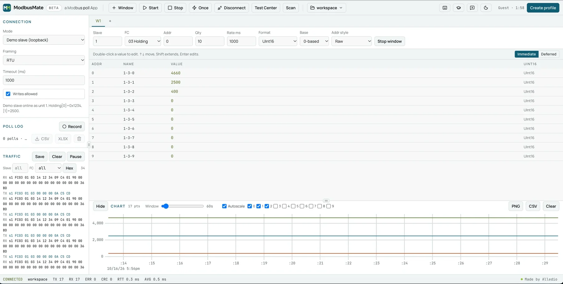
Open the traffic log. Every request and response shows in hex. RTU frames get a CRC check and ASCII frames an LRC check.
Filter by slave and function code to focus on one device. Use Pause to freeze the view while you read.
Watch for exception responses. A slave that rejects a request answers with the function code plus 0x80. For example, 0x83 instead of 0x03. Exception code 02 means “illegal data address”. So the link is fine, but the register does not exist.
Step 6: Scan if nothing answers
Maybe the address in the datasheet is not the address in the device. Run a device scan. It walks through unit IDs and shows which slaves answer.
If the scan finds the device at a new address, update your poll window. If the scan finds nothing, go back to Step 1 and Step 2. Our guide to the Modbus tester shows more ways to use the tool.
Step 7: Check the values and log the result
A working link is only half the job. The values must also make sense.
- Switch the format if a 32-bit value looks like nonsense. Try another byte order.
- Use Scaled (a × raw + b) to show tenths of a degree in real units.
- Set 0-based or 1-based addressing to match the datasheet.
Then press Record. Export the poll log to CSV or XLSX, or export the chart as PNG. Attach it to your commissioning report.
Testing on a live building? Untick “Writes allowed” first. Monitoring only blocks every write, so a test can never open a valve by mistake.
A one-minute checklist for site
Print this or save it on your phone. It covers the whole test in order.
- ☐ Adapter shows up as a serial port.
- ☐ A and B checked, common connected, termination at both ends only.
- ☐ Mode, baud rate, parity and stop bits match the datasheet.
- ☐ Slave ID is between 1 and 247.
- ☐ One poll window on a known register, with a small quantity.
- ☐ RX rises with TX, and CRC failures stay at zero.
- ☐ No exception responses in the traffic log.
- ☐ Values make sense after format, scaling and address base.
- ☐ Log recorded and exported for the report.
- ☐ Writes blocked if the building is live.
If one box stays empty, you know where to look. Fix that item before you move on. It is faster than changing three things at once and guessing which one helped.
No device on the desk yet?
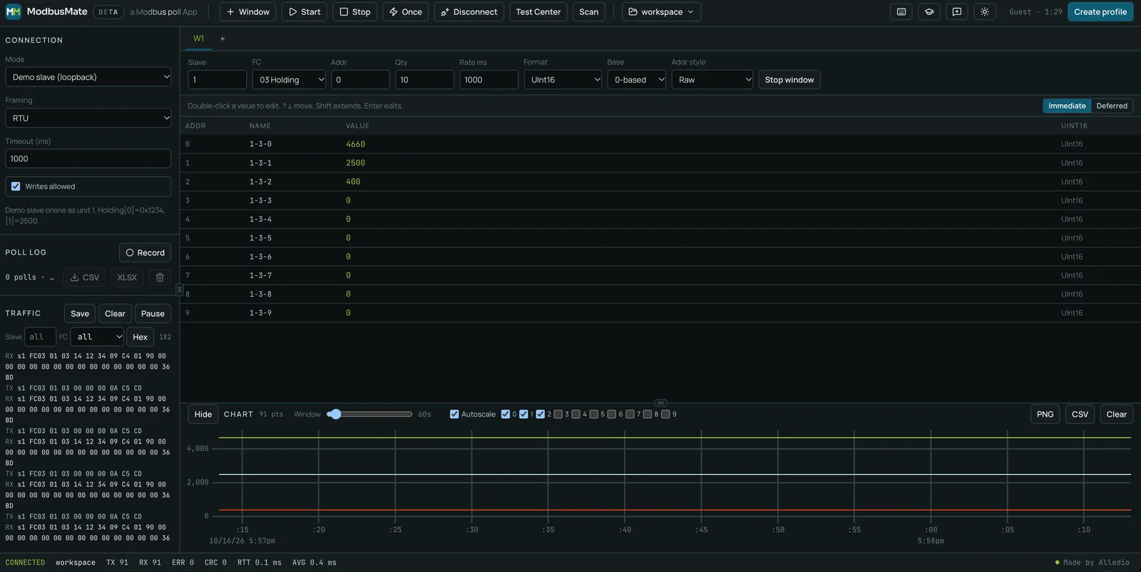
You can practise the whole flow without hardware. Choose Demo slave (loopback) as the connection mode. A simulated device answers as unit 1. It is the quickest way to learn the steps before you go on site.
Testing Alledio devices
Our Alledio room devices speak Modbus RTU. If you are commissioning an Alledio OEM Room Unit, these seven steps are exactly what we do on our own test bench.
FAQ
How do I know if Modbus RS485 communication works?
Poll one known register. If values arrive and the RX counter rises without CRC failures, the link works. ModbusMate turns arriving values green.
What is the most common cause of no response?
Usually wiring or settings. Check that A and B are not swapped. Then check slave ID, baud rate, parity and stop bits.
What do CRC failures mean?
The answer arrived, but it was damaged on the way. Common causes are noise, missing or wrong termination, or a baud rate mismatch.
Can I test Modbus RTU without installing software?
Yes. ModbusMate runs in Chrome, Edge or Opera on a desktop. You only need a USB to RS-485 adapter that shows up as a serial port.
Does this work for Modbus TCP?
Not with ModbusMate yet. Modbus TCP is coming soon. Today it supports Modbus RTU and ASCII over RS-485 or RS-232.
Run your first test now
Plug in your adapter and work through the seven steps on a real device, or on the demo slave.
Open ModbusMate and test your RS485 link
Want the full feature list first? See the ModbusMate product page. For the protocol itself, the Modbus Organization specifications are the official source.