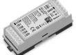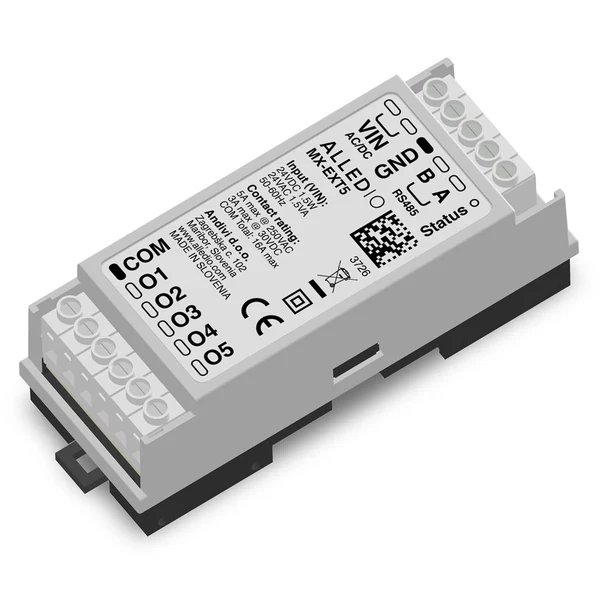
Three speed fan coil wiring looks like the easiest job on site: three speed wires, a common, two valves, done before lunch. Then commissioning starts, someone’s controller logic lets speed 1 and speed 3 overlap for a few milliseconds, and the fan motor gets a very bad day. This guide shows how to wire a 3-speed AC fan coil to relay outputs properly: one speed at a time, valves on the right common, interlocking that doesn’t depend on whoever wrote the controller program, and a Modbus setup you can repeat across 200 identical rooms. We use the Alledio MX-EXT Modbus relay module as the worked example.
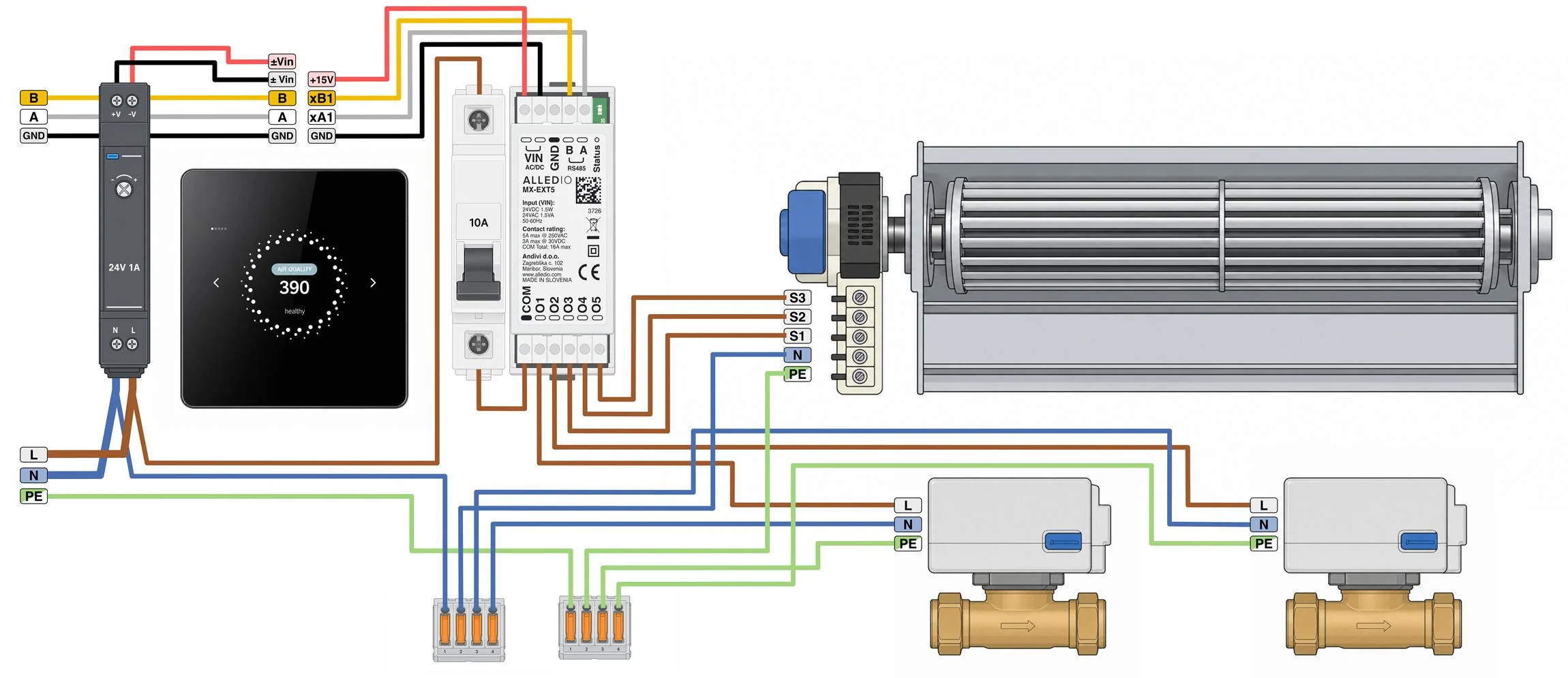
How a three-speed fan coil is switched
A typical fan-coil unit with a 3-speed AC fan has one speed input per speed (often labelled low/medium/high or S1/S2/S3) plus neutral and protective earth. Speed selection is simple: you connect the live supply to exactly one speed input at a time. Valves on a basic fan coil are on/off actuators, typically one for heating and one for cooling, each switched by its own contact.
In relay terms, that means:
- three contacts for the fan, one per speed, all fed from the same live supply;
- one contact per valve;
- a rule that two fan contacts are never closed together, including during the instant of switching from one speed to another.
The first two are wiring. The third is where projects go wrong, and it’s what most of this article is about.
Where should the fan relays live?
You have two broad choices. You can put the relays in the wall device, which brings mains voltage to the wall and limits you to whatever outputs that device has. Or you keep the wall device low-voltage and put a relay module in the fan-coil enclosure or room distribution board.
The Alledio approach is the second one. The Alledio Room Unit, Room Controller or OEM Thermostat stays on the wall with the user interface and control logic. The MX-EXT sits on a DIN rail inside the fan-coil enclosure or cabinet and switches the fan speeds and valves over RS485 Modbus RTU. The MX-EXT can also be used with other Modbus controllers. If you’re still choosing a module, our Modbus relay module buyer’s guide covers the selection criteria in detail. This article is about the wiring.
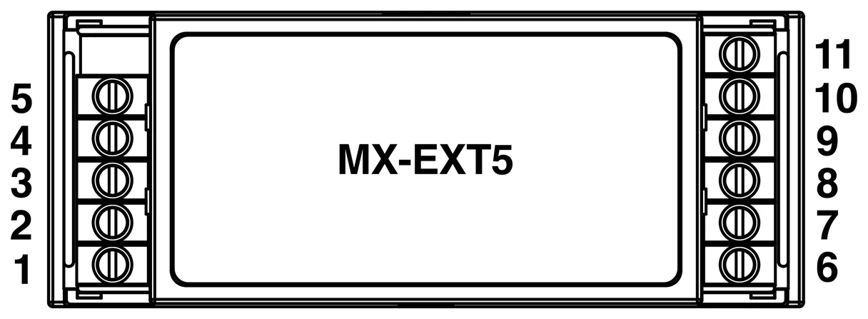
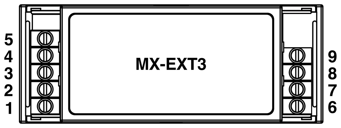
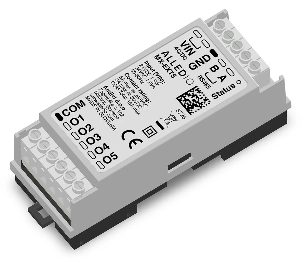
MX-EXT terminals at a glance
Both variants share the same supply and bus terminals. The difference is the number of outputs.
| Terminal | Name | Mode 1 function (fan coil, default) |
|---|---|---|
| 1, 2 | VIN | 24 V DC (18–42 V, polarity-insensitive) or 24 V AC ±25 % |
| 3 | GND | Signal ground, not PE. Recommended on long runs or mixed supplies |
| 4 | B | RS485 B |
| 5 | A | RS485 A |
| 6 | COM | Common for all outputs |
| 7 | O1 | Fan speed 1 |
| 8 | O2 | Fan speed 2 |
| 9 | O3 | Fan speed 3 |
| 10 | O4 | Valve (MX-EXT5 only) |
| 11 | O5 | Valve (MX-EXT5 only) |
Step-by-step: wiring a 3-speed fan coil to the MX-EXT5
Step 1 – Supply and bus
Connect 24 V AC or DC to VIN (terminals 1 and 2). DC polarity doesn’t matter. Connect RS485 A and B to terminals 5 and 4, using twisted pair with drain wire and foil wrap (or equivalent). Connect GND (terminal 3) on long runs or where devices use different supplies. Remember that it’s a signal ground: never use it as PE. The module is Class II and has no protective-earth terminal.
Step 2 – Protect the common
Bring the live feed for the fan and valves to COM (terminal 6) through an MCB or fuse matched to the load. The outputs and COM aren’t fused internally. Two limits apply:
- 5 A per output (resistive, 250 V AC), so no protective device above 5 A on any single output;
- 16 A total through COM, so any device on COM must not exceed 16 A.
Use at least 0.75 mm² per output and 2.5 mm² for COM. Terminals are M2.5 screw terminals (5.00 mm pitch, 0.5 N·m). Use ferrules and a 6 mm strip length.
Step 3 – Fan speeds on O1–O3
Wire the fan’s speed 1, 2 and 3 inputs to O1, O2 and O3 (terminals 7–9). That’s the factory default motor group, so the interlock works out of the box. Neutral and PE for the fan go to the fan, not through the module.
Step 4 – Valves on O4 and O5
On the MX-EXT5, wire the two on/off valve actuators to O4 and O5 (terminals 10 and 11). These contacts aren’t in the motor group, so either valve can switch independently of the fan speed.
Step 5 – Check the voltage band (the step people skip)
All outputs share one COM, so every load on the module must be in the same voltage band. The datasheet is explicit: don’t mix 230 V AC and extra-low voltage on the same COM. If your fan is 230 V AC and your valve actuators are 24 V, you can’t switch both from one MX-EXT. In that case use 230 V valve actuators, or switch the fan with an MX-EXT3 and handle the 24 V valves separately. Discovering this on the drawing board is free. Discovering it in the ceiling void isn’t.
Remapping: when the fan isn’t on O1–O3
Sometimes the panel layout or a standard wiring loom puts the fan elsewhere. The MX-EXT lets you move the interlock group to match. The datasheet example on the MX-EXT5 puts the valves on O1/O2 and the fan speeds on O3–O5, with the motor group set to O3–O5.
The group is a bit mask in holding register 8 (bit 0 = O1 … bit 4 = O5). The default is 0x0007 (O1–O3). For fan speeds on O3–O5, the mask becomes binary 11100, i.e. 0x001C. Whatever you wire, set the mask to match the fan contacts actually in use. An interlock that protects the wrong contacts is worse than none, because everyone assumes it’s there.
How the fan-speed interlock actually works
With motor mode on (holding register 3 = 1, the factory setting), the contacts in the motor group are mutually exclusive with break-before-make. The module opens one contact, waits a dead time, then closes the next. The dead time lives in holding register 6 (default 30 ms, adjustable 5–1000 ms).
What that means for the controller programmer:
- Single-coil writes (function 05) remain legal. The datasheet states that the driver performs break-before-make. Coils 0, 1 and 2 correspond to O1, O2 and O3.
- Multi-coil writes (function 15) that try to close more than one group contact are rejected as a whole with exception code 03 (ILLEGAL_DATA_VALUE). The module doesn’t guess which speed you meant.
- The same rule applies to the relay bitfield in holding register 0. In motor mode, a write must not set more than one bit from the group.
- Fan off simply means writing all three fan-speed coils to 0.
The function codes themselves (05 Write Single Coil, 15 Write Multiple Coils, 16 Write Multiple Registers) are defined in the official Modbus specifications.
One important caveat, straight from the datasheet: fan-speed interlocking is an application function, not a safety function. It prevents control mistakes. It doesn’t replace any protection the fan-coil manufacturer specifies.
Commissioning a floor of identical fan coils
Every factory-fresh MX-EXT ships at address 8, 115200 baud, 8N1 (the baud rate is fixed in current firmware). Twenty fan coils on one bus means twenty devices answering to 8. Don’t write the address register (holding register 2) while several devices still share address 8. Instead, use the module’s serial-number commissioning:
- Record each module’s unique factory serial (32 bytes, readable in input registers 3–18). The easy way is to read it on the bench, one module at a time, before installation.
- Write the target serial (holding registers 9–24) and the new address (holding register 25), then write 0xA55A to holding register 26 to commit. The datasheet recommends one broadcast function-16 write covering registers 9–26.
- Only the module with the matching serial takes the new address. The others ignore the write and stay silent. Then poll the new address.
Then finish the job:
- Termination: select 120 Ω via Modbus on the device at the end of the bus (the default is none).
- Interlock check: confirm motor mode and the group mask before anyone powers the fan.
- Function test: step through speed 1 → 2 → 3 → off, then each valve.
- Network: connect Modbus only to trusted, building-internal networks. It has no authentication or encryption of its own.
For more on bus layout and wiring between devices, see our article on Modbus daisy-chain connection in building automation.
MX-EXT5 or MX-EXT3 for your fan coil?
| Fan-coil configuration | Variant | Mode 1 assignment |
|---|---|---|
| 3-speed fan + two on/off valves on the same voltage band | MX-EXT5 | O1–O3 fan, O4/O5 valves |
| 3-speed fan only (valves handled elsewhere or on a different voltage) | MX-EXT3 | O1–O3 fan |
Both variants share the same 35 × 89.6 × 31.25 mm DIN-rail housing (EN 60715 TH35), weigh about 100 g, and are intended for a closed electrical cabinet, lockable control panel or fan-coil enclosure. Ingress protection is IP30 as installed, with an ambient range of −20 °C to +50 °C, non-condensing.
Safety notes that belong on the drawing
- Terminals COM and O1–O5 may carry 230 V AC. Installation and service are for qualified persons only, with all supplies isolated.
- The contacts provide micro-disconnection only. They aren’t a disconnecting safety device.
- Removing VIN opens all contacts. Contact state on a Modbus timeout is not a safety function, so don’t rely on it.
- The module is a Type 1 operating control, not a protective control.
Common three speed fan coil wiring mistakes
- Leaving the interlock to the controller alone. One bug and two speeds overlap. Use the module’s motor group as well.
- Moving the fan wires without moving the mask. If the fan isn’t on O1–O3, update holding register 8.
- Mixing 230 V fans and 24 V valves on one COM. One voltage band per common.
- Forgetting the COM limit. Up to 5 A per contact, 16 A total through COM.
- Using GND as earth. It’s a signal ground. The module is Class II.
Frequently asked questions
How do you wire a three speed fan coil motor to relays?
Feed the live supply through a protective device to the relay common, then wire one relay contact to each fan speed input (speed 1, 2, 3). Neutral and earth go directly to the motor. On the MX-EXT, that’s COM on terminal 6 and fan speeds on O1–O3 (terminals 7–9). Only one speed contact may be closed at a time.
Can two fan speeds be switched on at the same time?
They shouldn’t be. Use a relay module with fan-speed interlocking. On the MX-EXT, the default motor group (O1–O3) is mutually exclusive with break-before-make, and a multi-coil write that would close two fan contacts is rejected. That’s an application function, not a safety function.
Can one relay module switch a 230 V fan and 24 V valves?
Not on a shared common. The MX-EXT datasheet requires all outputs on one COM to be in the same voltage band, so 230 V AC and extra-low voltage can’t be mixed. Use 230 V valve actuators, or split the loads across separate devices.
Which MX-EXT variant do I need for a fan coil with heating and cooling valves?
The MX-EXT5. In Mode 1 it switches the three fan speeds on O1–O3 and two on/off valves on O4 and O5. The MX-EXT3 covers the three fan speeds only.
What happens to the fan if Modbus communication is lost?
Don’t treat communication loss as a safety mechanism. On the MX-EXT, removing the 24 V supply opens all contacts, and the datasheet states that contact state on a Modbus timeout is not a safety function. Anything that must reach a safe state needs its own protection.
Do I need a separate relay module if my room controller is Modbus-based?
It depends on where you want the mains switching. With Alledio wall devices, the relay module keeps the 230 V fan and valve switching in the fan-coil enclosure while the wall unit stays low-voltage. For the controller side, see our article on the OEM room controller for fan coil units.
Conclusion: wire it once, wire it right, repeat it 200 times
Good three speed fan coil wiring isn’t about the three wires. It’s about the rules around them: one speed at a time with break-before-make, valves on the same voltage band as the fan, a properly protected common, and an addressing plan that survives a floor of identical units. Build those rules into the relay module, and every room behaves the same way on day one and on day 1,000.
For background on adding relay outputs to a controller, read what a 5-channel Modbus relay extender is and when you need one. For full specifications, wiring diagrams and the register map, see the Alledio MX-EXT Modbus relay extender product page, or send the Andivi team your fan-coil schedule.